
You can first run a simulation through python.
Prerequesite
Download sample code
From GitHub website, Download code sample in zip file.
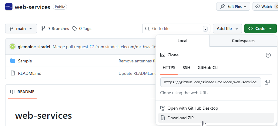
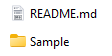
You can now unzip the archive.
Download python if you don't already have python on your machine
You can download the python distribution you want (e.g. Anaconda distribution).
During installation, make sure to select "Add Python to PATH" option. This will let you runing python command from you Windows prompt.
Run simulation
Reach the sample folder you have downoaded and unzipped.
Build your csv file with network information
Network file (.csv) must reference antenna and propagation model defined in input.json file
transmitter id;transmitter name;transmitter longitude;transmitter latitude;transmitter height;azimuth;downtilt;frequency;antenna;propagation model;calculation resolution;calculation radius;emitting power;comments
1;tx1;-122.294;47.05289;25;0;1;3600;Tarana_BN_3GHz_Compact_R0;Fixed Wireless Access;10;10000;0;
Configure input.json file
You can set in input.json all simulation parameters. Main parameters to adjust and check are :
-
credential : insert your LOGIN and PASSWORD
-
add antennas if needed
-
network file (.csv)
Propagation model and antenna used in network file must be configured in input.json
Run python script
On Linux environment
python3 client_simulations.py –i input.json -p
On Windows environment
python client_simulations.py –i input.json -p
If python is not recognized, you have to add Python to Windows Path. As an alternative, you can open Anaconda prompt if you have install Anaconda python distribution.
Get results
By default, results are downloaded and copied locally in the folder ScriptResults.
You will find one geotiff file per output (best signal, best server, ...), and one folder with per transmitter prediction results if you activated the option -p in the command line.
Geotiff include several code values.
In order to display it properly with a GIS tool, you need to adjust the colorscale with expected range.
Mapping between Web client and python client simulation parameters
If you are using Siradel Web Services web client, you can find below the mapping between parameters set in the web client and parameters fo be set in
|
Web client parameter |
input.json |
network file (.csv) |
|---|---|---|
|
Transmitters antenna |
antenna |
antenna |
|
Computation radius |
Computation radius |
|
|
Computation resolution |
Computation resolution |
|
|
propagation model |
propagation model |
propagation model |
|
Receiver height (m) |
receptionHeights |
|
|
Receiver antenna gain (dBi) |
emitting power |
|
|
Simulation margin (dB) |
emitting power |
|
|
Frequency |
frequency |
Simulation margin and Receiver antenna gain need to be integrated in network file receiver power. Example below shows how to integrate these parameters.
    Emitting power (dB) : 25
    Receiver antenna gain (dBi) : 10
    Simulation margin (dB) : 5
    Set your transmitter emitting power (in network.csv file) at : 25 + 10 -5 = 30